To check MOSFET lambda in LTspice, first inspect the model definition, then decide whether the parameter exists explicitly or must be extracted from simulated output curves. The keyword is normally spelled lambda and represented by λ. In the classic first-order MOSFET equation, it models the increase of saturation-region drain current with drain-source voltage and has units of V−1.
That simple interpretation is useful for hand analysis and teaching, but it is not universal. Many manufacturer power-MOSFET models are subcircuits containing controlled sources, capacitances, diodes, temperature functions, and internal transistors. Such a macromodel may reproduce output conductance without exposing one physical LAMBDA value.
Identify the model type before measuring
Open the symbol attributes or netlist and find the referenced model name. A primitive MOSFET normally points to a .model statement; a complex manufacturer model often points to a .subckt definition. Search the included library for that exact name, not just the marketing part number.
If a simple model supports a LAMBDA parameter, it may appear directly in the parameter list. Other compact-model levels use different equations and names. A subcircuit may contain several internal MOS elements, so a lambda found deep inside may not describe the terminal behavior of the complete device. This distinction follows the same model-awareness needed when studying how a MOSFET works.
Understand what lambda means
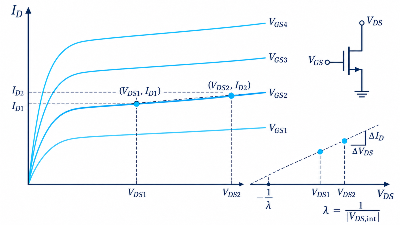
For a simplified long-channel device in saturation, one common approximation is ID ≈ ID0(1 + λVDS). Without channel-length modulation, the output curve would be flat. A finite λ gives the curve a positive slope and produces finite small-signal output resistance. Near a chosen operating point, gds = ∂ID/∂VDS, ro = 1/gds, and a rough effective λ is gds/ID.
This is a local approximation. Body effect, self-heating, mobility effects, drain-induced barrier lowering, quasi-saturation, and package resistance can change the curve. Power MOSFETs used as switches are especially different from textbook small-signal devices.
Create an LTspice output-curve sweep
Place the MOSFET with source and body connections appropriate to the model. Drive the gate from a DC source and sweep the drain supply with a .dc analysis. Use a nested sweep or a stepped parameter to generate several VGS curves. Keep the drain voltage, gate voltage, power, and temperature within model and device limits.
Plot drain current against VDS. Select a region that is clearly beyond the knee but not dominated by breakdown, current limiting, or obvious numerical artifacts. For a real power device, disable or account for self-heating only if the model documentation tells you how; otherwise the extracted slope may include electrothermal behavior.
Estimate an effective lambda from two points
Choose two nearby drain voltages V1 and V2 at one fixed gate voltage and record I1 and I2. Approximate gds = (I2 − I1)/(V2 − V1). Divide by the drain current near the midpoint to estimate λeff. Alternatively, fit a straight line over a narrow window and use its slope, which reduces cursor noise.
Report the bias and window with the number: for example, λeff at VGS, VDS, ID, and temperature. A single number without these conditions invites false comparisons. If you need amplifier gain, use the directly simulated small-signal output conductance or output resistance at the operating point rather than forcing a global lambda.
Use operating-point and small-signal results
An operating-point analysis can expose small-signal parameters for primitive devices, depending on model type and the LTspice display. You can also perturb VDS slightly around the bias point and calculate ΔI/ΔV. An AC test source provides another route when the bias circuit is linearized correctly.
Compare the result with the DC-curve slope. If they disagree, check sign conventions, current direction, sweep resolution, source degeneration, body connection, series resistance, and whether the measured current includes other branches. Protect the device model from unrealistic gate stress by observing the same limits discussed in MOSFET gate-oxide operation.
Know when lambda is the wrong target
For switch-mode loss, RDS(on), gate charge, output capacitance, reverse recovery, switching energy, thermal impedance, and avalanche behavior are usually more useful than lambda. For analog gain, gm and ro at the actual bias matter directly. For process or threshold research, use a validated compact model and extraction workflow rather than reading a single Level-1 parameter.
The article on gate-resistor tuning illustrates how parasitics and dynamic waveforms can dominate a switching design even when the static transistor model seems simple.
Engineering checklist
Archive the model file, vendor revision, symbol mapping, LTspice version, analysis directives, temperature, and numerical tolerances. Check that the expected model is actually loaded and that no duplicate model name silently overrides it. Sweep with enough resolution to reveal curvature, then repeat at several gate voltages and temperatures. Label extracted values as effective unless the model documentation explicitly defines LAMBDA.
Sanity-check the output curves against the manufacturer’s published characteristics, remembering that typical curves are not production guarantees. Avoid extrapolating a low-current lambda into high-current switching behavior. If the purpose is circuit gain or output impedance, simulate those quantities directly and confirm with sensitivity or bench measurements. A model is an engineering approximation, not proof that every production device will match.
Frequently asked questions
Is lambda the same as MOSFET threshold voltage?
No. Lambda describes output-current dependence on drain voltage in a simple saturation model; threshold voltage describes the onset criterion used by a model or extraction method.
Why can I not find LAMBDA in a vendor model?
The device may use a compact-model level or subcircuit that represents output conductance through other parameters and internal elements.
Can I calculate lambda as 1 divided by Early voltage?
For a local first-order MOS approximation, lambda is related to the inverse of an extrapolated Early voltage, but curvature and modern models make it bias dependent.
Does lambda matter for a fully enhanced power switch?
It is rarely the primary design parameter. Hot on-resistance, dynamic charge, switching energy, SOA, and thermal behavior are normally more useful.