To check a MOSFET on a motherboard, disconnect all power, verify that the rails have discharged, identify the device pinout, and use a digital multimeter in diode mode to compare drain-source, gate-source, and gate-drain readings. A near-zero drain-source reading in both directions can indicate a shorted MOSFET, but an in-circuit reading is not always conclusive because other components share the same rail.
Motherboards use MOSFETs in CPU and GPU voltage regulator modules, memory supplies, battery chargers, input protection, load switches, and fan or peripheral circuits. Most VRM devices are N-channel power MOSFETs or integrated power stages. Before testing, understand how a MOSFET transistor works, including its insulated gate and intrinsic body diode.
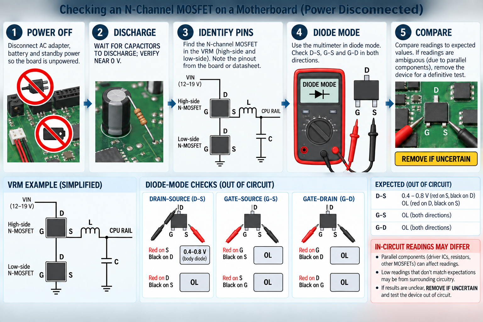
Safety before checking a motherboard MOSFET
- Shut the computer down and unplug the AC adapter or desktop power supply.
- Disconnect the laptop battery, CMOS battery when relevant, and any USB-C or docking power source.
- Hold the power button briefly to help the normal discharge paths operate, then wait for capacitors to discharge.
- Measure the input and suspect rails in DC-voltage mode. Continue only after they are near 0 V.
- Use ESD precautions and support the board on a nonconductive surface.
Never use resistance, continuity, or diode mode on an energized board. The meter applies its own test voltage, and external power can damage the meter or motherboard and create misleading results. Large primary-side capacitors in desktop power supplies can retain hazardous voltage; test the motherboard only after it is separated from mains-powered circuitry.
Identify the MOSFET and its pins
Do not assume that every eight-pin package has the same pinout. Search the top marking, board schematic, or component datasheet. Packages may connect several pins to the source or drain, expose a large thermal pad, or contain two MOSFETs in one body. DrMOS and smart power-stage packages also include a driver and current sensing, so a three-terminal test procedure does not fully apply.
In a synchronous buck VRM, the high-side MOSFET normally connects the input supply to the switch node. Its drain is near VIN and its source is near the inductor-side switching node. The low-side MOSFET connects that switch node to ground. Its drain is at the switch node and its source is usually at ground. The gate connects to a driver through a small resistor or direct trace.
The article how to wire a MOSFET explains why gate voltage must be referenced to the source and why high-side connections differ from low-side connections.
Start with visual and thermal evidence
Look for a cracked package, burn mark, displaced component, corroded area, or damaged gate resistor. A failed MOSFET does not always look burned, and a scorched device may be the victim of a short elsewhere. Inspect the controller, driver, ceramic capacitors, inductors, and nearby power stages before deciding what to replace.
If the board previously powered long enough for thermal imaging, a rapidly heating MOSFET can identify the affected rail. That observation is not proof that the MOSFET caused the fault. Current flowing into a shorted downstream capacitor or processor rail can also heat a healthy switching device. Review why MOSFETs get hot before interpreting temperature alone.
Quick in-circuit drain-source check
With the board unpowered, put the meter in diode mode. On an N-channel MOSFET tested by itself, the body diode normally conducts with the red probe on source and the black probe on drain. A typical meter may show roughly 0.3 to 0.8 V, depending on the device and test current. Reversing the probes should show open loop while the gate is discharged.
On the board, measure drain to source in both directions and record the values. A reading near 0 V in both directions is suspicious, especially if the same package has visible damage. However, the meter may be reading through other MOSFETs, controller protection structures, inductors, or output capacitors. A CPU core rail can have very low resistance by design.
Compare equivalent phases in a multiphase VRM. If one phase reads differently from several otherwise identical phases, the outlier deserves investigation. If every phase shows the same low reading, the shared load or output rail may be responsible.
Check gate-source and gate-drain insulation
Measure gate to source in both probe directions, then gate to drain in both directions. An ordinary discrete MOSFET should normally appear open or very high resistance at the low voltage supplied by a multimeter. A persistent near-zero reading between gate and source or gate and drain strongly suggests gate-oxide damage or an external circuit short.
In-circuit gate readings can be affected by the gate resistor, driver IC, pull-down network, and protection clamps. If the gate appears shorted, measure on both sides of the gate resistor. This helps distinguish the MOSFET from a failed driver output.
Why continuity mode is not enough
A continuity beep only reports that resistance is below the meter’s threshold. It does not identify a body-diode junction, reveal polarity, or distinguish a designed low-resistance rail from a failed transistor. Use diode-mode values and resistance trends, compare phases, and consult the circuit.
Capacitors can make a reading start low and then rise as they charge from the meter. That changing value is different from a solid short that stays near zero. Reverse the probes, wait for the reading to settle, and compare with a known-good board when possible.
When to remove the MOSFET
If in-circuit results are ambiguous, remove the device or lift the relevant terminal with controlled hot-air and preheating procedures. Once isolated, discharge the gate through an appropriate resistor and repeat the tests:
- Drain-source: body-diode drop in one direction and open in the other for an uncharged N-channel device.
- Gate-source: open or extremely high resistance in both directions.
- Gate-drain: open or extremely high resistance in both directions.
- Drain-source short: a stable near-zero reading in both directions indicates a failed device.
A basic gate-charge test can demonstrate switching out of circuit: charge the gate positive relative to the source, observe lower drain-source resistance, then discharge the gate through a resistor and confirm that the channel turns off. This is only a functional screen. It does not test breakdown voltage, hot RDS(on), gate charge, switching loss, leakage at rated voltage, or safe operating area.
Find whether the MOSFET or the rail is shorted
After removal, measure the empty board pads. If the drain-source path on the board is still shorted, another component or the load is faulty. If the board short disappears and the removed device reads shorted, the MOSFET is confirmed as part of the fault.
For a low-voltage rail, technicians may use a current-limited bench supply to inject a voltage below the rail’s normal maximum and locate the heating component. This is an advanced procedure. The safe voltage and current depend on the rail, processor, controller, and connected devices. Never inject an arbitrary voltage, and never exceed a component’s normal operating range.
Check the circuit before fitting a replacement
A replacement MOSFET can fail immediately if the gate driver is stuck high, the complementary device is shorted, the PWM controller has lost dead time, or the load remains shorted. Check the gate resistor, bootstrap diode and capacitor, driver supply, low-side and high-side partner, output capacitors, and resistance from the rail to ground.
Match the original device’s channel type, drain-source voltage, gate-voltage range, hot RDS(on), current capability, gate charge, package pinout, thermal pad, body-diode behavior, and switching characteristics. The practical MOSFET selection guide explains why a same-size package is not enough.
Powered waveform checks are for trained technicians
If passive tests pass but the motherboard still fails, a trained technician may power it from a current-limited source and examine gate, switch-node, and rail waveforms. Use probes rated for the voltage and bandwidth, a short ground connection, and differential or isolated measurement where required. Never attach an earth-referenced oscilloscope ground to a node that is not at earth potential.
Look for missing gate pulses, incorrect dead time, excessive ringing, a collapsed driver supply, or one phase that does not share current. A multimeter alone cannot reveal these dynamic problems.
Frequently asked questions
Should a motherboard MOSFET beep in continuity mode?
It may beep through the body diode, an inductor, a parallel MOSFET, or a low-resistance load. A beep alone does not prove failure. Check polarity and diode-mode voltage, compare equivalent phases, and isolate the device when needed.
Why does a CPU rail read almost shorted to ground?
Modern processors operate at low voltage and high current, so the rail’s normal resistance can be very low. Compare with service data, a known-good board, or the behavior after isolating the inductor or MOSFET.
Can a MOSFET test good on the board and still be faulty?
Yes. A device can pass a low-voltage meter test but leak at operating voltage, have excessive on-resistance, switch slowly, or fail when hot. Dynamic or curve-tracer testing may be required.
Can I replace only the visibly burned MOSFET?
Only after checking the complementary MOSFET, driver, controller, gate components, capacitors, and load. Replacing the visible casualty without correcting the initiating fault often destroys the new part.