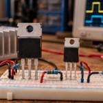
A MOSFET amplifier is a circuit that uses a metal-oxide-semiconductor field-effect transistor to increase a signal’s voltage, current, or power. The input changes gate-to-source voltage, which changes drain current. A load and power supply convert that current change into the desired output. MOSFET amplifiers range from tiny sensor front ends to RF stages, audio output stages, and high-efficiency Class D power amplifiers.
The word “amplifier” describes the circuit function, not a special MOSFET type. Device structure, bias, feedback, cooling, and the surrounding network determine whether the stage behaves linearly or as a switching power amplifier.

How a MOSFET creates gain
The gate is insulated from the channel, so it presents high DC input resistance. When gate-to-source voltage changes above the operating region, drain current changes according to the device transconductance and load. In a common-source circuit, increasing drain current increases the voltage drop across the drain load, so drain voltage falls: the output is amplified and inverted.
Threshold voltage only indicates a small specified current and is not a useful linear bias target. For device fundamentals, read how a MOSFET transistor works. Practical gain depends on transconductance, drain resistance, source degeneration, output resistance, and loading.
The main amplifier configurations
A common-source stage provides voltage gain and inversion. A source follower, or common-drain stage, has voltage gain near one but offers high input impedance and lower output impedance, making it a buffer. A common-gate stage has low input impedance and can work at high frequency. Differential pairs compare two inputs and form the front end of many operational and power amplifiers.
Power audio output stages often use complementary or quasi-complementary source followers. Class A, AB, and B describe conduction angle and bias; Class D instead switches MOSFETs and reconstructs the audio with a filter and load.
Biasing a linear MOSFET stage
A linear amplifier needs a quiescent operating point that leaves room for the output to move in both directions without clipping. The bias network must tolerate threshold and transconductance spread, supply variation, and temperature. Source degeneration and negative feedback stabilize current and reduce distortion. Coupling capacitors may block DC while setting the low-frequency response with surrounding resistance.
For a power stage, establish bias with the actual heatsink temperature and a controlled current limit. Thermal tracking matters because insufficient compensation can increase idle current as the assembly warms. Excessive bias wastes power; insufficient bias increases crossover distortion.
Small-signal gain and bandwidth
At midband, the gain can be estimated from transconductance multiplied by the effective drain load, adjusted for source degeneration and feedback. At low frequency, coupling and bypass capacitors create poles. At high frequency, gate-source and gate-drain capacitances, especially the Miller effect, reduce bandwidth and increase the input drive current.
PCB capacitance, source impedance, package inductance, and the next stage’s input also matter. RF amplifiers require impedance matching and stability analysis, not just an audio-frequency gain formula. A network that maximizes gain may oscillate when connected to a real source or load.
Linear versus Class D MOSFET amplifiers
In a linear amplifier, MOSFETs can hold substantial voltage and current at the same time, so they dissipate heat continuously. In a Class D amplifier, the output devices switch mostly on and off, reducing device dissipation; pulse-width or related modulation carries the signal and an output network drives the speaker. Switching introduces dead-time distortion, EMI, gate-drive demands, and filter design.
The car-audio overview at what MOSFET means in car audio explains how MOSFETs appear in both the power supply and output stage. “MOSFET amplifier” does not by itself identify the class or quality.
Choose a device for the operating mode
For a linear output stage, examine DC safe operating area, thermal stability, transconductance, capacitance, breakdown voltage, current, and package thermal resistance. Some modern switching MOSFETs have excellent RDS(on) but limited linear-mode capability because cells may not share heat evenly. Use parts documented for linear service when sustained voltage and current overlap.
For Class D, compare on-resistance at temperature, gate charge, output charge, body-diode behavior, switching speed, package inductance, and driver compatibility. The guide to MOSFET heating helps separate conduction, switching, and thermal-interface losses.
Build and test without oscillation or thermal failure
Keep gate loops short, add gate resistors or stoppers where required, decouple each supply rail close to the active stage, and separate high-current returns from small-signal ground. Verify stability into capacitive and reactive loads. Use current limiting on first power-up and begin without an expensive speaker connected. Check DC offset, idle current, clipping symmetry, frequency response, noise, and case temperature.
Power MOSFETs need a calculated cooling system; see how to calculate MOSFET heatsink size. Test the hottest ambient, lowest load impedance, maximum signal duration, blocked airflow, and turn-on and turn-off transients.
Frequently asked questions
Does a MOSFET amplifier always use one transistor?
No. A basic stage can use one MOSFET, while practical audio and RF amplifiers may use differential inputs, drivers, complementary output devices, parallel devices, feedback, and protection.
Is a MOSFET amplifier better than a BJT amplifier?
Neither is automatically better. Noise, gain, distortion, impedance, power, bandwidth, cost, device matching, and thermal design determine the result.
Is Class D the same as digital audio?
No. The output transistors switch, but the signal path and modulation can represent an analog input. Class D describes the power-output operating method.
Can any power MOSFET be used in a linear amplifier?
No. Check the DC safe operating area and manufacturer guidance. A switching-optimized MOSFET may be unreliable under sustained linear stress.