Check a Schottky diode by removing power, discharging capacitors, and measuring it in both directions with a multimeter’s diode-test mode. A healthy device normally shows a relatively low forward-voltage reading in one direction and open circuit in the other. A shorted diode reads low both ways; an open diode reads open both ways.
Those are screening results, not full characterization. Schottky forward voltage depends on test current, and reverse leakage rises strongly with voltage and temperature. In-circuit components can also create misleading readings, so lift one lead when the result is ambiguous.
Make the circuit safe
Disconnect every source, including batteries, USB cables, solar inputs, and auxiliary rails. Verify zero voltage and discharge capacitors through an appropriate resistor. High-voltage power supplies can retain lethal energy. Never use resistance or diode mode on an energized circuit.
Inspect the package for cracks, discoloration, lifted pads, corroded leads, or a damaged cathode mark. Obtain the part data sheet and schematic if possible. The article on what a Schottky diode is explains its metal-semiconductor junction and lower forward drop.
Identify anode and cathode
On many axial devices, a band marks the cathode. SMD codes vary, and dual diodes may use common-cathode, common-anode, or series connections. Confirm the manufacturer drawing instead of guessing from package shape. For a discrete diode, forward current flows conventionally from anode to cathode.
If the marking is unreadable, diode mode can help identify orientation only after the device is isolated from confusing parallel paths. Record the result rather than repeatedly charging nearby capacitors.
Run the forward-bias test
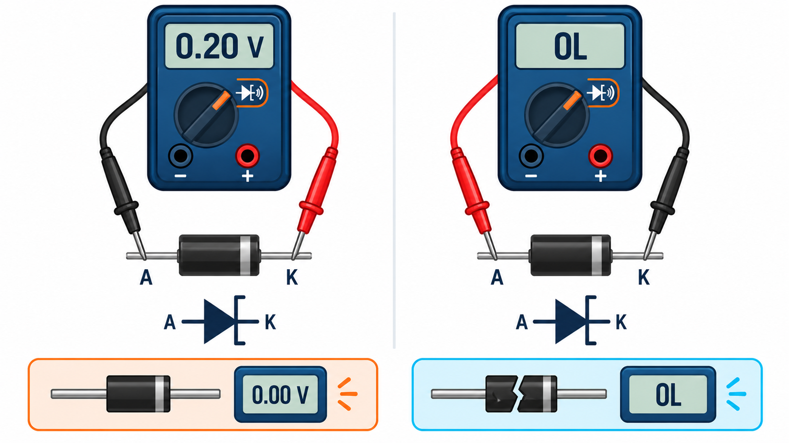
Select diode mode. Place the red probe on the anode and the black probe on the cathode. The meter sources a small current and displays forward voltage. Many Schottky devices show roughly 0.15 to 0.45 V at low meter current, but this is not a universal pass band. High-current or high-voltage Schottky parts and cold devices may differ.
Compare with a known-good identical part and the data-sheet curve. Poor probe contact or oxidized leads can create an unstable or high reading.
Reverse the probes
Place red on cathode and black on anode. A good diode normally shows OL at the meter’s low reverse-test voltage. A low reading in both directions suggests a short or a parallel circuit path. OL in both directions suggests an open device, wrong pins, poor contact, or a meter whose test voltage is insufficient for the junction arrangement.
The general method for checking diode direction in rectifier circuits applies, but Schottky leakage requires extra interpretation.
Know when in-circuit testing lies
Transformer windings, inductors, resistors, other diodes, MOSFET body diodes, capacitors, and IC protection structures can connect around the diode. A capacitor may make the reading change slowly. Compare equivalent channels or reverse the probes, but lift one diode lead for a definitive basic check. Avoid overheating or damaging the pad during removal.
For a dual Schottky package, test each internal junction using the documented common pin. One half can fail while the other still appears normal.
Test leakage and loaded operation when needed
A diode can pass meter tests yet leak excessively at its operating reverse voltage, fail when hot, or develop excessive forward drop at load current. A current-limited bench test can measure forward voltage at a specified current. Reverse-leakage testing requires a controlled source, series limiting, appropriate meter, guarding, and voltage safely below the rating.
Never use an uncontrolled supply to test breakdown. Schottky diodes commonly have more reverse leakage than p-n rectifiers, and the data sheet specifies it at particular voltage and temperature.
Practical design review
If the diode came from a failed supply, diagnose the surrounding circuit. A shorted Schottky may be caused by excessive surge current, overheating, reverse-voltage spikes, transformer or inductor faults, poor cooling, or an output short. Check capacitors, synchronous rectifiers, snubbers, controller timing, solder joints, and load behavior before installing a replacement.
Select the replacement by repetitive reverse voltage, average and peak current, surge rating, forward drop at operating current, reverse leakage at hot temperature, package thermal resistance, capacitance, and qualification. The comparison in when to use a Schottky diode helps determine whether Schottky, ultrafast p-n, SiC, or synchronous rectification best fits the circuit.
After replacement, begin with current-limited input and monitor diode temperature and output ripple. Check startup, full load, rapid load release, and high input voltage. A repeated failure usually indicates unresolved circuit stress rather than a defective new diode, so stop testing until the current path and waveform are understood.
Frequently asked questions
What reading should a Schottky diode show?
Many show about 0.15 to 0.45 V in diode mode, but the correct value depends on device, meter current, and temperature. Use the data sheet and a known-good comparison.
Why does my Schottky diode show some reverse conduction?
It may be an in-circuit path or normal leakage that the meter displays unusually. Isolate one lead and compare with the specified leakage test.
Can a Schottky diode test good cold and fail hot?
Yes. Reverse leakage increases with temperature, and bond or package faults can be intermittent. Loaded thermal testing may be needed.
Can I replace a Schottky diode with a silicon rectifier?
Only after checking forward loss, switching speed, reverse recovery, voltage, current, leakage, thermal behavior, and circuit timing. It is not automatically interchangeable.