Test an SMPS chopper stage by checking the switch and gate path with power removed, then correlating controller bias, gate-to-source voltage, drain voltage and sensed current on a documented, current-limited low-voltage setup. A switch that never receives a pulse, a switch that fails to respond to a pulse and a controller that deliberately stops pulses require different checks.
Identify what the switch controls
Chopper usually means the power switch and drive that periodically apply energy to an inductor or transformer. Trace the exact topology and identify the MOSFET source reference, control bias supply, current-sense point and protection inputs. The switch-node waveform of a flyback differs from a buck or boost. Use the circuit documentation and the switch-mode supply design overview to establish the expected waveform.
Offline primary-side circuits remain hazardous after disconnection and may have no earth-referenced measurement node. Live primary testing belongs to qualified service personnel using rated instruments and procedures. Never defeat scope protective earth or connect a grounded probe clip to a live floating node. The powered checks below describe a documented low-voltage development fixture.
Start with the unpowered stage
Remove supply and stored energy. Inspect the fuse, switch package, gate resistor, driver return, sense resistor, clamp and surrounding copper. Compare static drain-to-source and gate-insulation readings with the expected device polarity and a good unit. The body diode and other parallel paths can change a meter reading. Use the MOSFET multimeter guide to isolate a suspect device before declaring it shorted.
If the switch has failed, inspect the rectifier and magnetics for shorts and check that the driver can hold the gate off. A failed clamp or overloaded output can destroy a new switch as soon as energy returns. Record readings and the fault history before changing parts.
Follow the startup in time order
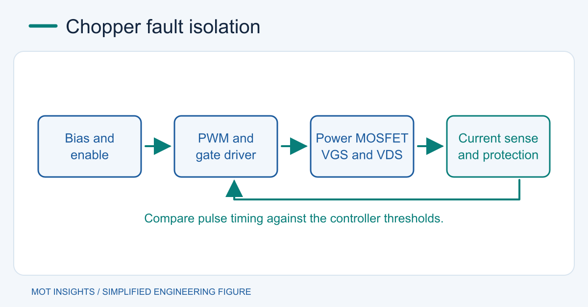
On an appropriate fixture, start with conservative energy limits and the manufacturer’s recommended load and sequence. Capture controller bias and enable first. A bias supply that rises to startup and drops below its undervoltage threshold can cause recurring bursts. Check the auxiliary bias path and its load. A stable bias rail with an active fault input can also explain an idle gate.
Measure VGS directly across the device. If the controller commands pulses but the MOSFET gate does not respond, check the driver supply, gate resistor and return path. If VGS appears adequate but VDS fails to move, check for missing bus voltage, a damaged switch, an open path or a measurement-reference error. In a boost or flyback expect drain behavior appropriate to its energy transfer interval.
Use current sense to interpret shutdown
A short pulse that ends when sense voltage reaches its documented limit can indicate real overcurrent, a saturated inductor or a turn-on spike entering the sense path. Compare with a properly rated current probe or validated shunt. A smooth rise followed by a sudden increase in slope can indicate falling incremental inductance. Verify probe timing and distinguish a current-sense artifact from actual drain current.
If switching stops after several pulses, correlate bias voltage, sense threshold and feedback before replacing parts. Hiccup mode deliberately pauses and retries. Review the short-circuit protection sequence for typical timing. Validate startup, steady load and thermal behavior after correction, then record VGS, VDS and current together. For device selection after the underlying fault is resolved, share the measured stress with MOT.