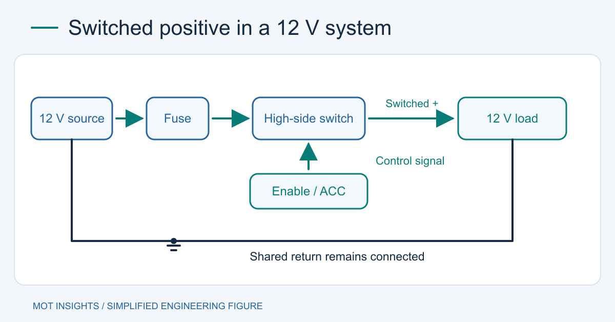
A switched positive lead delivers a positive voltage relative to the system return when its controlling switch is on. The load’s ground can remain connected while the positive feed goes on and off. On a vehicle, a switched lead may follow an accessory or ignition state. On electronic equipment, it may be a switched output or a low-current enable signal. The pinout and current rating determine which job it can do.
Identify three different functions
| Lead function | Behavior | What it is for |
|---|---|---|
| Constant battery or +12 V | Stays energized when the controlled circuit is off | Memory supply, battery feed or always-on branch |
| Switched positive power output | Supplies current to a load while enabled | Rated lamps, modules or other loads |
| Enable, ignition sense or ACC signal | Changes level with the operating state | Logic input, switch control or another documented low-current function |
A positive lead may read battery voltage on a meter with its controlled load disconnected. This by itself gives no current rating. A module can also have pull-ups, off-state leakage or periodic diagnostics that produce a reading on a high-impedance meter when the output is supposed to be off. Start with the wiring diagram or data sheet and confirm the designated ground pin, control states, continuous rating, transient rating and protection.
High-side switching and low-side switching
High-side switching opens or closes the connection between +12 V and the load. Low-side switching controls the return between the load and ground. A low-side circuit can leave the load’s positive terminal energized after it stops drawing current. Ground-referenced interfaces may work more naturally with high-side switching because the module return stays at its reference potential. Check for a separate path through a USB cable, signal return or second power supply. That path can feed an otherwise disabled module. High-side and low-side MOSFET wiring
A remote switch on a power supply may control its main output via an enable input. This is a different connection from a switched positive output that supplies current. Remote inputs can use a dry contact, active-low logic or an isolated interface. The manual determines whether an external voltage is allowed. Remote enable on a switching power supply
Verify the lead on a low-voltage system
With the equipment de-energized, identify the connector and ground reference from the wiring diagram. Use a correctly ranged voltmeter. Measure the open-circuit voltage relative to the specified return in each documented state. On a vehicle, compare OFF, ACC and RUN if available, and note that the system may drop accessory power during cranking or retain it for a short time after shutdown. Take the observations from a stationary, secured vehicle, and leave safety-critical circuits alone.
If the documentation identifies a power output, test it with an appropriate protected load within its rating, then compare voltage at the source and load. Assume an approved 2 A test load measures 12.4 V at the source and 11.9 V at the load. The 0.5 V drop suggests about 0.25 Ω for the complete feed and return path at that current. Measure across the switch, wiring segments and return individually to locate the drop. For an unknown signal, keep the meter high impedance and identify the circuit before applying a load.
Use a high-current load with a low-current signal
If a controller lead is rated for tens of milliamps and the intended load draws amps, give the load its own fused feed. Use the lead to control a compatible relay driver or a protected high-side switch. Size the wire, fuse and contacts or switch for operating current, inrush and available fault energy. Place the feed fuse close to its supply point. A module’s off-state leakage, reverse voltage, supply transients and inductive turn-off must all fit the selected hardware. A bench supply reading of 12 V represents a different electrical environment from a vehicle battery system. MOSFET protection for inductive loads
Frequently asked questions
Is ACC always a 12 V power output?
Some systems provide an accessory power branch and others expose an ignition-sense signal or report state over a data bus. Match the exact connector and pin number to the service documentation before connecting anything.
Can I identify a switched lead by color?
Use the equipment pinout and verify voltage in the relevant states. Installers and manufacturers may assign different functions to the same color, and an older harness can have modifications.
Before connecting a second supply or an always-on branch, trace the return and power paths and check for unwanted current feeding back into a disabled rail.