Switch-mode power-supply repair should begin with safety, not component replacement. A mains-powered SMPS can retain lethal voltage after it is unplugged, and its primary side may be directly connected to the line. If you are not trained to work on energized high-voltage electronics, replace the supply or use a qualified technician.
For trained repair work, document the symptom, identify the topology, inspect without power, discharge and verify stored energy using an approved procedure, then diagnose one functional block at a time. Never defeat isolation, protective earth, fuses, insulation, or safety spacing to make a unit run.

Understand the hazardous zones
The primary side includes the input fuse, EMI filter, bridge rectifier, bulk capacitor, startup circuit, primary controller, switch, and transformer primary. The bulk capacitor may hold hundreds of volts DC. The secondary can also deliver destructive current, and some auxiliary outputs are not isolated. Mark the isolation barrier and protective-earth connections before probing.
If the architecture is unfamiliar, review what a switching power supply is. Use correctly rated probes, meters, isolation practices, PPE, and a bench arrangement appropriate to the product and local safety rules.
Record the symptom before disassembly
Note whether the unit is dead, cycling, ticking, shutting down under load, producing excess ripple, overheating, or damaging a fuse. Record input conditions, load, LEDs, odor, noise, and previous events. Confirm the external cable, connector, switch, load, and source first. An overloaded or shorted downstream board can make a healthy supply enter protection.
Photograph wiring, insulation sheets, pad locations, screw lengths, and earth bonds. Look for cracked solder joints, browned board areas, swollen capacitors, loose connectors, conductive debris, water damage, and damaged insulation. Visual clues guide testing but do not prove the only fault.
Test unpowered components methodically
After safe discharge and verification, check the fuse, inrush limiter, MOV, bridge rectifier, main switch, current-sense resistor, startup resistor, snubber parts, secondary rectifiers, and output rails for shorts. Measure semiconductors out of circuit or lift a lead when parallel paths make readings ambiguous. An open fuse usually indicates a fault; replacing it alone can cause a second violent failure.
The article on rectifier diodes helps interpret forward and reverse tests. Electrolytic capacitors require capacitance, ESR, leakage, temperature rating, ripple-current rating, and visual inspection—not appearance alone.
Diagnose startup and control behavior
Many supplies charge a controller supply through a startup path, then an auxiliary transformer winding sustains it. If the controller supply reaches its start threshold and repeatedly collapses, suspect auxiliary supply, overload, feedback, or short-circuit problems. If it never rises, inspect startup components and controller leakage. Use the exact controller datasheet and schematic where available.
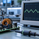
Gate-drive waveforms must be measured with an appropriate isolated or differential method. A grounded oscilloscope clip on the primary can short the line through protective earth. Do not float ordinary grounded equipment as a workaround.
When the MOSFET or fuse has failed
A shorted power MOSFET can be the result of excessive drain voltage, poor gate drive, controller failure, transformer saturation, current-sense error, snubber failure, overheating, or a secondary short. Check the driver, gate resistor, clamp, current-sense path, transformer, rectifiers, and load before installing a replacement. Match voltage, current, RDS(on), gate charge, package, avalanche, switching, and thermal requirements.
The background article on MOSFET heat and loss explains why a part with a higher current rating may still fail in the same circuit.
Power up with controlled energy
After unpowered checks, use the service method specified for the equipment: appropriate isolation, current limiting, protective enclosure, and a known load. Stand clear of exposed primary circuitry and keep one-hand and probe-placement practices consistent with professional training. An incandescent limiter can be useful in some legacy contexts but is not a universal or standards-compliant solution.
Bring the input up only when the procedure calls for it. Watch input current, controller supply, output voltage, ripple, gate drive, switching-node stress, temperature, and abnormal sound. Shut down immediately if current rises unexpectedly or the converter pulses erratically.
Validate the repair before return to service
Replace safety-critical parts only with approved equivalents. Restore insulation barriers, sleeving, pads, glue, earth hardware, creepage, clearance, and flame-rated components. Perform the required dielectric, earth-bond, leakage, and functional tests for the product class. Then test no-load, nominal load, full load, startup, shutdown, line range, and transient behavior.
Confirm output ripple with a short probe loop and suitable bandwidth method. Verify thermal performance after equilibrium. The design checklist in how to design an SMPS is useful for understanding protections and operating corners that a repair must preserve.
A disciplined fault-isolation checklist
Separate observations from conclusions. For each stage, record expected voltage or waveform, actual measurement, instrument and reference point, power state, and the next safe test. This prevents a secondary symptom—such as a controller supply collapsing—from being mistaken for the root cause. Compare channels or identical units only when variants and component tolerances are understood.
After replacing parts, inspect both sides of the board under magnification. Remove flux or debris using a process compatible with the product. Confirm diode, capacitor, transistor, and connector polarity; resistor values; solder wetting; isolation slots; sleeving; and wire routing. Refit every shield and insulator before the final energized test. Keep a repair log with the failed parts, causal diagnosis, substitutions, test loads, temperatures, ripple, safety-test results, and burn-in duration. If the causal chain cannot be established or required safety tests are unavailable, do not return the supply to service.
Frequently asked questions
Why does an SMPS fuse blow immediately?
Common causes include a shorted bridge, power switch, bulk capacitor, PFC stage, rectifier, or wiring fault. Find the underlying short before installing another fuse.
Can I test the primary with a normal oscilloscope?
Only with a safe, correctly rated measurement setup and training. A grounded probe can create a dangerous short. Use equipment and procedures appropriate to mains circuits.
Should all electrolytic capacitors be replaced?
Not automatically. Replace parts that fail measured electrical, thermal, lifetime, or visual criteria with correctly rated low-ESR components where required.
Is a repaired supply safe after the output returns?
Not necessarily. Protection, isolation, earth, ripple, thermal, load, and fault tests must also pass before it returns to service.