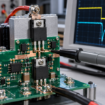
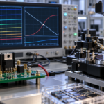
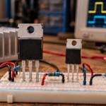
Yes, using a MOSFET as a switch usually reduces device heat compared with using it as a linear dropping element. When fully on, drain-source voltage is small; when fully off, drain current is small. The product of voltage and current is therefore low for much of the cycle. During each transition, however, voltage and current overlap, and the on-state still has resistive loss.
Switching does not eliminate heat. It changes where and when loss occurs, and it can move loss into the driver, diode, magnetics, capacitors, snubber, and EMI filter.
Why linear operation can run hot
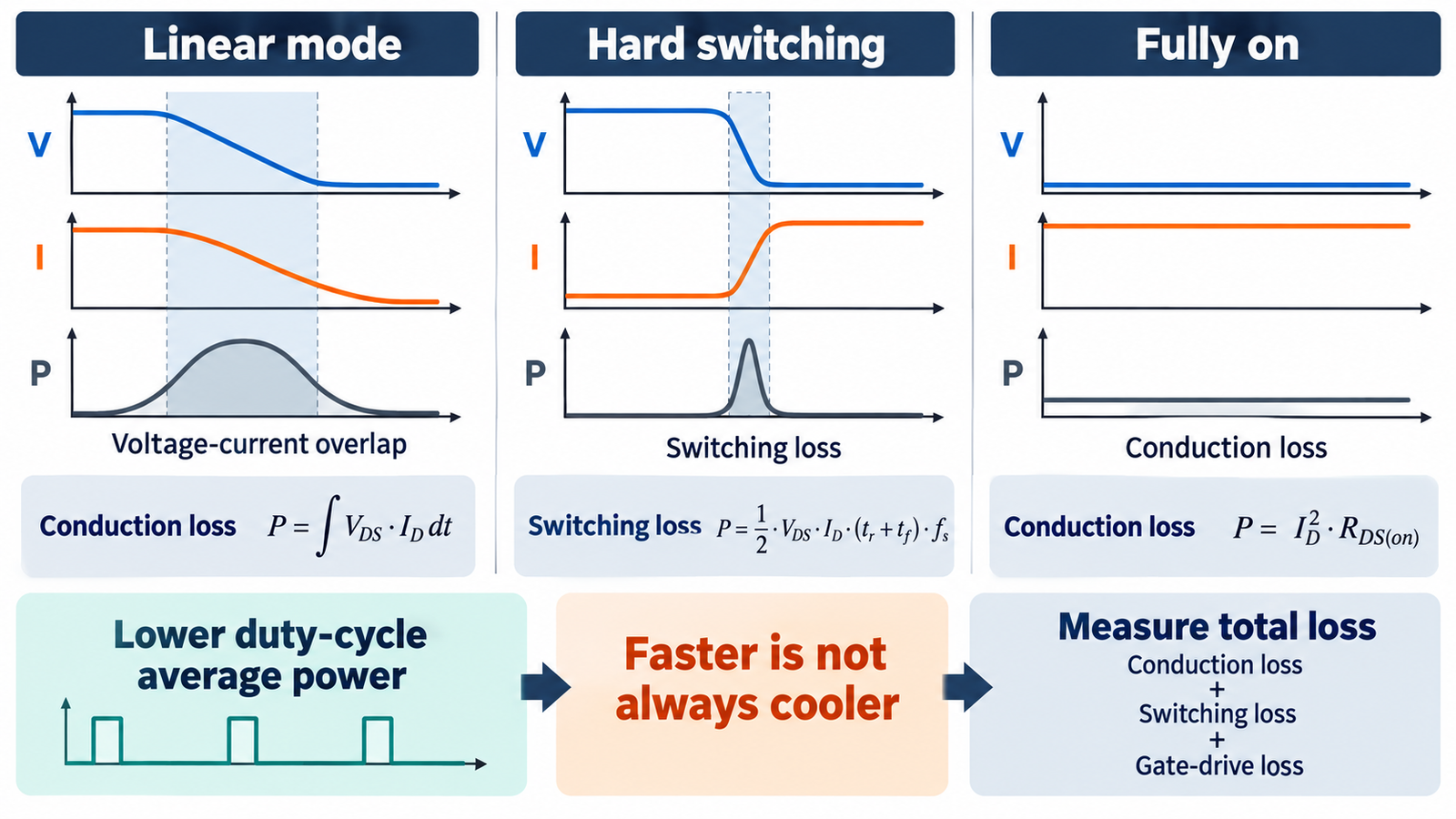
A linear MOSFET used to drop voltage may carry load current while supporting a large drain-source voltage. Its dissipation is approximately VDSID. Dropping 8 V at 5 A produces 40 W in the transistor, before other losses. The device also needs adequate DC safe operating area because current can crowd into local hot regions.
The thermal primer at why MOSFETs get hot explains the link between dissipation, thermal resistance, and junction temperature.
Conduction loss remains while on
An enhanced MOSFET behaves approximately like a resistance, so conduction loss is IRMS2RDS(on). Resistance rises with junction temperature, and the data-sheet value depends on gate voltage. High current, long duty cycle, weak drive, package resistance, and hot operation can make conduction loss dominant even when switching is perfect.
Use RMS current rather than average current for a pulsed waveform. Include current ripple and body-diode intervals. A low room-temperature resistance printed on the front page is not a complete worst-case value.
Transitions create switching loss
During turn-on and turn-off, current and voltage coexist while the gate traverses its Miller plateau. A rough estimate scales with bus voltage, current, combined transition time, and switching frequency. Real loss also includes nonlinear capacitances, diode reverse recovery, loop inductance, dead time, and circuit topology. Faster edges shorten overlap but can increase ringing, overshoot, EMI, and false turn-on.
Use the MOSFET gate-resistor tuning guide to balance transition energy against electrical noise and stress.
Frequency changes the heat balance
Energy lost per transition is multiplied by the number of transitions per second. Doubling frequency roughly doubles loss terms that occur once or twice per cycle, although operating conditions and soft switching can change the relationship. Gate-drive power also grows with total gate charge, drive-voltage swing, and frequency. Output-capacitance energy is repeatedly charged and discharged.
Higher frequency can shrink inductors, transformers, and capacitors and improve control bandwidth. The optimum is the frequency that minimizes total size, cost, and loss while meeting transient and EMI requirements—not simply the fastest the transistor can switch.
PWM reduces average load power differently
Pulse-width modulation delivers controlled average energy by changing duty cycle. A heater, motor, or LED sees repeated full-amplitude pulses and its electrical or mechanical time constants smooth the result. The MOSFET spends relatively little time in its linear region. This is often far more efficient than inserting a variable resistance.
Correct freewheel paths are essential for inductive loads. The connection examples in how to wire a MOSFET show why a gate pull resistor, suitable driver, and flyback or recirculation path matter.
Soft switching can reduce transition energy
Resonant and quasi-resonant converters may arrange near-zero voltage or current at a switching event. Zero-voltage switching can recover or redirect output-capacitance energy and reduce turn-on loss; zero-current switching reduces current overlap. Benefits depend on load range, circulating current, timing, magnetic design, and parasitic elements.
Soft switching is not free. Circulating current may increase conduction loss, and losing the intended condition at light load or during transients can restore hard-switching stress. Measure the real waveforms.
Optimize and verify the complete system
Select voltage rating with transient margin, then compare hot RDS(on), gate charge, output charge, reverse behavior, package inductance, and thermal path. Use a strong but controlled driver, compact commutation and gate loops, local decoupling, correct dead time, and an appropriate snubber. Calculate every significant loss at worst-case conditions.
The broader design workflow in designing a switch-mode power supply shows how control, magnetics, EMI, protection, and thermal validation interact. Verify efficiency, waveforms, and junction temperature on the final PCB.
How to prove the thermal benefit
Compare the proposed switching control with the linear alternative at the same delivered load power and conditions. For the MOSFET, separate on-state energy, turn-on energy, turn-off energy, output-capacitance energy, reverse or diode energy, and gate-drive energy. For the linear circuit, calculate voltage-current overlap throughout the control range. Include losses in the inductor, diode, driver, filter, and wiring so the comparison does not merely move heat out of the transistor and ignore it.
Measure input and output power with instruments suited to pulsed waveforms, then correlate the difference with component temperatures. Check low duty cycle, full duty cycle, stalled or shorted load, minimum and maximum supply, and the frequency extremes. If a switching design is unexpectedly hot, inspect the gate plateau, dead time, switch-node ringing, reverse recovery, and actual gate voltage before buying a larger heatsink. Correcting the waveform often saves more heat than changing the cooling hardware.
Frequently asked questions
Does faster switching always reduce heat?
No. Faster edges can reduce overlap loss but increase ringing, EMI, capacitive current, reverse-recovery stress, and overshoot. There is an optimum edge rate.
Does PWM make a MOSFET run cool?
It often reduces loss compared with linear control, but temperature still depends on current, duty, resistance, frequency, transitions, cooling, and load behavior.
Can a MOSFET have zero switching loss?
Ideal models can, but real devices have finite charge, capacitance, resistance, parasitics, driver loss, and timing error. Soft switching can greatly reduce selected terms.
Why does a low-RDS(on) MOSFET still overheat?
Switching loss, inadequate gate voltage, poor layout, high frequency, diode recovery, weak cooling, or operation outside safe area may dominate.